New domain and blog

New domain and blog
Please head over to my new domain to view my blog and current projects
Showing posts with label Raspberry Pi. Show all posts

Monday, 2 September 2013

LabVIEW and Raspberry Pi TCP/IP Communications

A few months ago I did the LabVIEW Connectivity course at National Instruments UK. I really enjoyed it but haven't got around to trying any of the concepts out yet. Last week I decided to write a TCP/IP chat program working between LabVIEW running on my Windows laptop and Python running my Raspberry Pi.


On the left of the you can see the LabVEIW front panel running the server. On the right is the putty terminal running a Python client. At the moment I only have the functionality to connect one client to the server. 

This little project got me thinking and I learnt quite a few new concepts. 

LabVIEW Server:

I used the LabVIEW example finder to get started. 


The LabVIEW server starts off my listening for connections. I have set a 60 sec timeout for this wait. Once connected, there are two parallel loops running. One loop is used to transmit strings and the other loop is used to receive strings. 

To transmit a string, the user types the string in the User Input control and presses the Return key. An end of line character is then concatenated onto the string which is transmitted using TCP Write. 

To receive a string, the TCP Read function listens with a timeout of 100 ms. If a string is received, it is concatenated onto the Response String indicator. 

Python Client:

This is where things got interesting. I needed to use threads, timeouts and sockets, each of which I have never used before. This client was written in Python 3.2.


I ended up using two threads. One for the transmit and the other for the receive controls.

I used a global variable which is used to stop the threads when the client or server is stopped. I also needed to use a timeout in both the transmit and receive thread because the recv() and readline() methods blocked the program flow which locked up the threads if the client was stopped.

With the timeout set, I could monitor the global variable and return cleanly from the thread when the client or server was stopped.

First start the LabVIEW server, then within 60 sec run the Python client. The connection will be established and you will be able to send strings between LabVIEW and the Raspberry Pi. To stop the programs, either use the Stop button in LabVIEW or CTRL+C in Python. Both methods will stop both the server and the client.

To download the LabVIEW and Python code, use this link.

I am sure there are many methods to do what I have done here, even better, cleaner ones. My Python is all self taught and only being used for my hobbies. I am using my Raspberry Pi for what is was designed for; learning. If you can recommend a better way to do this, please let me know because I am always keen to learn something new.

Greg

Thursday, 29 August 2013

Raspberry Pi: 3x3x3 LED Cube

If you do a web search for LED cubes, you will notice that they have been built so many times and anything less than 8x8x8 is a bit of a waste of time. Knowing all of this, and basically because I am bored out of my mind, I decided to go ahead and build one with old parts lying around at home. 

I ended up with a small 3x3x3 LED cube connected to my Raspberry Pi. I chose 3x3x3 because no extra hardware is needed. All I needed to do was find 27 LED's which I took off an old LED matrix sign board. 


The basic concept is this; the cube, in this case 3x3x3, is made up of columns (9) and layers (3).On each layer, all the cathodes are connected together and in each column, the anodes are connected together. Therefore, 12 ouputs are needed to control all 27 LED's.

By driving the layer output low and the column output high, the specific LED will turn on. Driving both the layer and column output low, will turn the LED off. By sequencing what LED is on when, you can draw different patterns. The bigger the cube, the better patterns can be drawn.

Update:
I have drawn up a schematic to show the hardware connections for the cube and the cube to he RasPi's GPIO header.


You can download a schematic here.

Take a look at this 32x32x32 LED cube that someone build.


I wrote my code in Python3.2 using the Rpi.GPIO library.

Greg

Sunday, 2 June 2013

Raspberry Pi: MCP23008 Port Expander

I have been wanting to get an MCP23008 I2C port expander connected to my Raspberry Pi for quite a while. I finally got one and during my breaks from LabVIEW CLD exam preparation, made the circuit on some strip board. 


Using the Quick2Wire Python I2C library makes getting this working really quick and easy. Just make sure you place your LED's the correct way around. I spent a bit of time debugging the I2C until I thought of checking the obvious. 

Currently I only have the outputs working as I didn't have any switches with me. I'll add two switches and get that going next. 

Here is the code that I used. I set up a little menu to select which LED to turn on or off. 


Next I plan to get the software PWM working so that I can connect up to Cheerlights. Need to do some more studying and then will get that going. Also need some RGB LED's first.

Until next time, happy coding.

Greg

Wednesday, 24 April 2013

Raspberry Pi temperature profile using LabVIEW

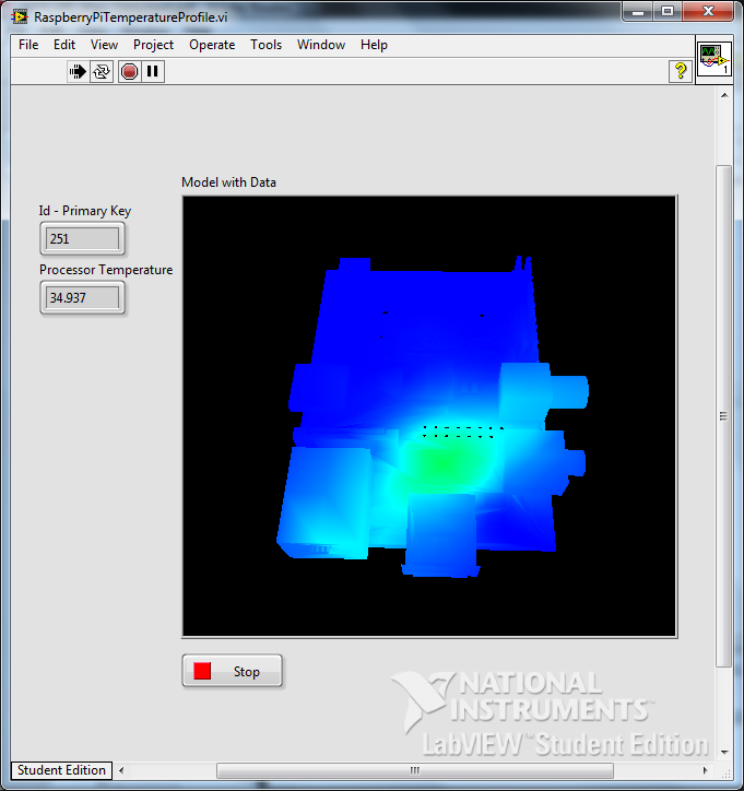
Connected to my Raspberry Pi is a DS18B20 temperature sensor which I have mounted inside the case roughly above the processor. I wanted to map the temperature profile inside the case and have a visual representation of it. To do this I joined up a Python script, an SQLite3 database and LabVIEW.


I only have one temperature sensor connected and the RasPi doesn't run very warm so this image is rather exaggerated. I'll explain a bit more later.

So I started off by writing a Python script that runs on my RasPi. It measures the temperature and then logs it to a SQLite3 database that I store in a shared folder on a mounted USB flash drive. I have accelerometer data in the database too, but that will be added a bit later.


That is all that happens on the RasPi. Next I wrote a LabVIEW program that queries the database over the network to get all the data. I need to do a bit of work on my query to just return the last line of data but that I'll add in future versions.

To query the SQLite3 database, I used the this toolkit which works really well and is super simple to get set up. Once I have the temperature, I need to display it on in user interface. This is where Sensor Mapping Express VI comes in really handy.


All you need to do is point to your .stl file and select where you want to the temperature sensors to sit on the RasPi. I used this model which I converted using Google SketchUp. This is where I had to use four dummy senors to be able to show the temperature difference. I have set the outside 4 sensors to 0 degrees Celsius and only sensor 0 is getting the temperature from the database. With more sensors this can be made a lot more accurate. As I said earlier, this is just to prove a concept for now.

Every 100ms I query the database, build an array with the temperature data and then apply it to the Sensor Mapping Express VI. The temperature profile then changes according to the surface temperature of the RasPi.

Here are the colours that I used for my mapping:

Temperature vs Colour mapping:
0 Celsius R-0 G-0 B-255
21.25 Celsius R-0 G-255 B-255
42.5 Celsius R-0 G-255 B-0
63.75 Celsius R-255 G-255 B-0
85 Celsius R-255 G-0 B-0

I have already connected up an ADXL345 accelerometer which is acquiring tilt and pitch values, so my next step is to be able to move the  model in LabVIEW as I move my physical RasPi. Should be some fun for a few more hours.

If you want a copy of my code, you can grab it over here.

Please feel free to leave any tips, comments or questions below.

Greg

Monday, 22 April 2013

Route static files for BottlePy web framework

I have been using BottlePy on my Raspberry Pi for quite some time. I really like the simplicity of the framework and the ease at which you can get something up and running. The one issue I had, was that you could not load static css or js files. 

There are ways around this, like placing your files in Gist and linking to the raw code, but this can be an issue when you want to run your webserver 'offline'. The documentation is not very clear on how to do this, so here is what I did to get it working properly. 

This is the template that I use to route the static files. This is part of my main python code that runs the server.

Then all you need to do is add your file names in the .tpl file. By doing this, your css, or js files can be stored locally so they can still be served if you are offline. 

That is about it. I hope this helps because I really find this framework great to use and works flawlessly on my Raspberry Pi.

Greg

Tuesday, 16 April 2013

Raspberry Pi: Direct connection to Windows 7

This is something I have been wanting to try for quite some time but never really found much info on how to do it. Well I sat down the other day to get it done and realised that it is MUCH easier than I expected.

My objective is to directly connect my Raspberry Pi to my laptop using an ethernet cable. In the next few months I am going to be away from a decent internet connection but I still wanted to do some work on my RasPi. So my Google searching started, finished and here is what to do.

The process uses a built-in feature of Windows 7 called Internet Connection Sharing (ICS). In a nutshell, you can use any Windows computer with more than one network connection, WiFi and LAN, and share the connection to other computers. 

Firstly you need to set up the settings on Windows. You need to go to the properties of your disconnected LAN connection and click on the sharing tab. Then check the box to allow other network users to connect through this internet connection.


The tricky thing to set up is the IP address that you are going to give the RasPi. You need to check the TCP/IPv4 settings under the Networking Tab. I picked an IP address and gave my RasPi a static address so that I know what it is when ever I use this connection.

Next you need to power up your Raspberry Pi and connect to it some way. Either use a WiFi connection that is already set up, an ethernet connection to your router or using the serial port on the GPIO.

You then need to set up the IP address by editing the interfaces file.
sudo nano /etc/network/interfaces
Change the part of the file that refers to your eth0 connection to look similar to below. You might have other settings in there like WiFi IP addresses and passwords but just leave those alone.
iface eth0 inet static 
address 192.168.137.184 
netmask 255.255.255.0

Once you have saved the interfaces file, send the shutdown command so that you can change over the connections. Once powered off, directly connect your RasPi ethernet port to your Windows ethernet port. You should be able to use both straight-through and cross-over cables. Now power up the RasPi.

Once booted up, you should be able to log in with Putty to the static IP address that you set above. 

And that is pretty much it. Another cool thing by connecting this way is that you should be able to power your Raspberry Pi from your computer USB port. This makes transport really easy as all you need is an ethernet cable and a USB cable to get up and running. 

Hope this helps and if you have comments or questions, please leave them below and I'll get back to you as soon as I can.

Greg

Tuesday, 12 March 2013

Raspberry Pi: NAS server

I have been wanting to set up my Raspberry Pi as a Network Attached Storage (NAS) drive for quite some time. I eventually got a chance yesterday to give it a go. Unfortunately the Raspberry Pi USB port can't power my external hard drive and I don't have a USB hub at the moment, so I just used a 16GB flash drive.

First you need to format your external drive with NTFS. Then place a file on it. Any file will do. I chose a text document so that I can open it and view it on the Pi. Once you have set up your drive, turn off your RasPi, plug the drive into the USB port and then turn on the RasPi. It is safer to plug the USB in when the RasPi is off because some versions don't have poly fuses on the USB ports.

Once booted up, log in and check to see if the drive is connected.
  • sudo fdisk -l

You can see that my connected drive is right at the bottom. The drive is called sda and because there is only one partition, it is called sda1.

Next you need to create a folder where your drive is going to be mounted into. I called mine myHadrDrive. You also need to give the folder root access so that when you connect to it you are able to read from it and write to it.
  • sudo mkdir /mnt/myHardDrive
  • sudo chmod 0777 myHardDrive
Next you need to mount the hard drive to the folder that has just been created. Open fstab and add the following line to the bottom of the file where it reflects your setup.
  • sudo nano /etc/fstab

Mount the drive
  • sudo mount -a
Now we need to install and set up the Samba server. This will allow a windows machine to connect to the RasPi over the network. Start by installing the following packages using apt-get.
  • sudo apt-get install samba
  • sudo apt-get install samba-common-bin
  • sudo apt-get install ntfs-config
  • sudo apt-get install ntfs-3g
Once all of those packages are installed, edit the Samba configuration file. It took me a while to get this right but with the help of this video, I managed to get it. 
  • sudo nano /etc/samba/smb.conf
Replace the entire file with the following:
#======================= Global Settings =======================
[global]
workgroup = WORKGROUP
server string = raspnas server
netbios name = raspnas
dns proxy = no
### Logging
log file = /var/log/samba/log.%m
max log size = 1000
syslog = 0
panic action = /usr/share/samba/panic-action %d
### Authentication
security = user
map to guest = pi
#======================= Sharered Folders =======================
[media]
path = /mnt/myHardDrive
guest ok = yes
guest account = ftp
browseable = yes
read only = no
create mask = 0777
directory mask = 0777
writeable = yes
admin users = everyone
#==========================================================

A few points to note:
  • WORKGROUP is the workgroup that the drive will be connected to
  • raspnas is the name of he drive on the network
  • path is the folder that you set up earlier
  • Change the file according to your setup
Lastly you need to restart the Samba service and add the user to the Samba database
  • sudo service samba restart
  • sudo smbpasswd -a pi
Now your Samba server is set up. You still need to do one last thing. You need to make sure that the drive gets connected at startup.
  • sudo apt-get install autofs
Add the following line to the bottom of the config file
  • sudo nano /etc/auto.master

Reboot your RasPi and then you should be able to log on to the shared drive using your Windows machine.

I hope this has helped anyone who was stuck. If you still have any problems leave a message in the comments and I'll try help as best I can.

Greg

Tuesday, 26 February 2013

TI C2000 LaunchPad unboxing

Yesterday I received my TI C2000 LaunchPad from Element14 for a road test. I have been working with the MSP430 LaunchPad for a few weeks now and am really enjoying what it can do. I am therefore really excited about getting into the C2000.


I plugged it in and got the default program up and running pretty quickly. With it connected to a terminal, you can see the temperature change and get logged. Next I wanted to get the standard flashing LED program running to get a basic feel for the development board.

I assumed that the two development boards, MSP430 and C2000, would be similar, but I was wrong. There is quite a difference in setting up the device and getting it running. I eventually got a simple flashing LED program running.

The example projects are also set up quite differently and it takes a bit of time to figure out how things are laid out.

To get going, I am going to go through the LaunchPad schematic and also the F28027 device datasheet. Once I know what is connected to which port and peripheral, then I can get going properly.

My plan is the following:
  • Get the flashing LED's working - DONE
  • Get serial communications working. LaunchPad to Putty
  • Get SPI working
  • Connect up CC1101 433MHz module to get RF communications working
  • Connect to RaspberryPi USB port and use as a port expander and RF master
For now that is what I plan to do. I will log my progress here as I manage to get each part working. For now I better get reading and start understanding the development board that I have in front of me.

Greg

Wednesday, 12 December 2012

Raspberry Pi meets TI LaunchPad MSP430

A few weeks ago I got a TI LaunchPad. With the help of a few tutorials I managed to get the basic input, output and UART working. As most of the examples that I could find are for CCS, I decided to go that route instead of IAR.

My next step was to get my LaunchPad working with my Raspberry Pi via the USB port. After a bit of playing around and installing a few programs, I managed to get it to work. Below is how I got a program  written, compiled and programmed onto the LaunchPad from the Raspberry Pi.

First you have to install a few programs with apt-get.
$sudo apt-get install binutils-msp430
$sudo apt-get install gcc-msp430

$sudo apt-get install msp430mcu

$sudo apt-get install mspdebug

$sudo apt-get install msp430-libc
You might have to run
$sudo apt-get update
before installing the modules.

Next run mspdebug to make sure that there are no errors. If there are no errors type exit to close the debugger.
$sudo mspdebug rf2500
Now that you have everything installed, we need to create the program. I use nano text editor to write my program.
$sudo nano button_ISR.c

This program uses the two LED's and one push button on the LaunchPad. When the button is pressed, an interrupt is generated and then the LED's are toggled.

Close nano saving the changes.

The program then needs to be compiled.
$sudo msp430-gcc -mmcu=msp430g2553 -g -o BUTTON_ISR button_ISR.c
The program should compile without any errors and now you are able to run the debugger.
$sudo mspdebug rf2500
Now program the device
prog BUTTON_ISR
and run the program
run
CTRL+c will stop the program running and exit will close the debugger.

In the next post I will show you how to communicate between the TI LaunchPad and Raspberry Pi via hardware UART and the USB connection.

Greg

Monday, 10 December 2012

Raspberry Pi: Edimax EW-7811UN WiFi Dongle

I recently bought myself an Edimax Wifi dongle to use with my Raspberry Pi. My router is hidden away so I got tired of running a network cable to my Raspberry Pi. The Edimax WiFi dongle was ideal as it is really inexpensive and very small.

It took a while for me to get it set up correctly but eventually I got there. To set up the WiFi connection, you either need a ethernet cable plugged into your Raspberry Pi or you need to connect via the serial port. I connected via the serial port with a FTDI USB to UART converter as this made it much easier to know when the network was connected. 

First of all plug the dongle into one of the USB ports and then reboot.I have not tested this in a USB hub but I am sure it will work the same. To make sure that the dongle has been started, run 
ifconfig
and make sure that wlan0 can be seen.


The next step is to see if your Raspberry Pi can see your wireless network. Run the following command and look for your network.
sudo iwlist wlan0 scan

Under 'Cell 01' I can see my network. Take not of your ESSID and you will also need your network password.

Once you have established that your Raspberry Pi can see your wireless network, you will need to edit the network interfaces file.
sudo nano /etc/network/interfaces
You will need to add the following:
  auto wlan0
allow-hotplug wlan0
iface wlan0 inet dhcp
wpa-ssid 'your ESSID'
wpa-psk 'your password'
Your interfaces file should now look like this. Note that I have set a static IP address so if you still use DHCP then you will not need the static IP address settings like I have.


Restart your network connection by running
sudo /etc/init.d.networking restart
and then run
ifconfig
and you should notice an IP address assigned to wlan0.

Now reboot your Raspberry Pi to make sure that everything is working in order.
sudo reboot
If your connection is up and running after the reboot, then you are all set to go wireless.

Greg

Monday, 29 October 2012

Raspberry PI: Bottlepy and Twitter Bootstrap

I have been using my Raspberry Pi for the last few months quite a lot. I am currently working on a temperature/environment monitor that logs temperature, using a DS18B20, and light conditions using an optical sensor. I also have two LED's and two buttons to test basic input and output.

I am developing the application in python using the BottlePy framework. I chose the BottlePy framework as it is a single file that you add, it is very small and it works with Python 3. To control my GPIO's, I am using the Quick2Wire library. To display the temperature data, I am using Google Charts.


This is a picture of the main temperature logging page so far.

However, the purpose of this post is to show how to integrate BottlePy and Bootstrap by Twitter. According to their website, Bootstrap is a "Sleek, intuitive, and powerful front-end framework for faster and easier web development."

To display this, I am going to use my GPIO code which reads buttons and turns on LED's through a webpage. 


To start off we need python file that will run as the server. Below is a snippet of code. The @route shows that this particular function will be run when /gpio us entered into the browser. The webpage is broken up into four sections. The first controls LED 1, the second controls LED 2, the third gets the state of both buttons and light sensor and then the fourth runs a .c file to flash the LED's.


Now we need to have a look at the html code that creates the webpage. By default, Bootstrap works with the user downloading the .css and .js file. These are then statically linked to the html code. When using the BottlePy framework, I haven't found a way to return a webpage template, AND a static file. Therefore I have found a link where the .css and .js files have been hosted. By using these links, you only have access to the default settings, but they are enough for what I am wanting to do.


You have to link to the .js and .css file and then by using certain classes that have been defined and explained on the Bootstrap website, you can get nice looking buttons, navigation bars, and tables. They have many options to use but these are the three that I used here for my site. 

When a button on the website is pressed, it sends the value back to the python function and the python code will perform the task. With the Flash LED button, the python code calls a .c file that has been compiled and runs when called. 

When requesting the button state, I return hex formatted colours to show the state of the buttons. These the colour in the table. 


The red shows that Button 1 has been pressed, the Green shows that Button 2 is not pressed and the Blue shows that the light level is currently light.

There are many different elements that can be added by using the Bootstrap framework. The documentation is really clear and easy to follow with many examples. 

If you get stuck or need some more explanations give me a shout.

Greg

Thursday, 27 September 2012

Raspberry Pi: Changing time zones

By default the time zone on the Raspberry Pi image is set the the UK. As there is no RTC on the Raspberry Pi, when ever it is turned on, the time is synced. To set the time zone to your local area, in my case South Africa, the configuration of the tzdata package needs to be changed.

sudo dpkg-reconfigure tzdata


Select your territory.


Then select your local time zone.


As you can see the time zone has now been changed.

Greg

Monday, 10 September 2012

Raspberry Pi: Using Bottlypy to control GPIO

I have been trying for a few days now to get control over the GPIO pins through a webserver. There are a number of tutorials on the web but having very little web programming experience, I struggled to understand and follow the tutorials. 

After working through a number of examples, and not getting what I want, I came across the bottlepy framework. The tutorial on their website and the todo example show enough ways on how to get data to an html page and how to get data from an HTML page.

I have been super busy at work and also trying to get it to work so haven't had a chance yet to do a bit of an explanation on what I did.

To download the files I used click here.

You will need to edit your IP address in the index.py file.

Change to the directory on your Raspberry Pi and run $ python3 index.py

In your browser navigate to IPaddress:8080/index then follow the links. Have a look in index.py to see what pins I have used for the inputs and outputs.

Sorry this is so vague but as soon as I get a chance I will update this post with some more explanations.

Greg

Wednesday, 29 August 2012

Raspberry Pi: GPIO input and output

So I got my Raspberry Pi yesterday and am super excited. I feel like a 10 year old on Christmas morning. I had already loaded the the Raspbian image onto an SD card so as soon as I got it I powered it up and away it ran.

The first thing that I wanted to get working was the GPIO pins. I did a bit of reading and some basic python examples and away I went. Have a look at this website for a very decent crash course in python.

The first thing you need to do is import the GPIO module. This can be installed from here

Then you need to tell python that you are going to use the Raspberry Pi's pin numbers when referencing the ports. The direction of the port is then set.

Once the setup is complete, you can start your code. In my hardware, I connected a push button switch to pin 11 and pin 18 and an LED to pin 3 and pin 5.

import RPi.GPIO as GPIO

#use the Raspberry Pi pin numbers
GPIO.setmode(GPIO.BOARD)

#set the input with pull up control
GPIO.setup(11, GPIO.IN, pull_up_down=GPIO.PUD_UP)
GPIO.setup(18, GPIO.IN, pull_up_down=GPIO.PUD_UP)

#set the output pins
GPIO.setup(3, GPIO.OUT)
GPIO.setup(5, GPIO.OUT)

while 1:
 if GPIO.input(11):
  GPIO.output(3, False)
 else:
  GPIO.output(3, True)

 if GPIO.input(18):
  GPIO.output(5, False)
 else:
  GPIO.output(5, True)

Above is the python code that I used. If you want to download the file you can get it here.

Once you have the file saved, run it in python and by pressing the buttons, the LED's will turn on. To stop the program running, press CTRL+z.

Greg