New domain and blog

New domain and blog
Please head over to my new domain to view my blog and current projects

Tuesday, 10 December 2013

LabVIEW: Getting started with LVOOP

I have been trying to get a handle on LVOOP for many months now but have been battling to get the concept into my head. I understand the concept of OOP, or at least I think I do, but really battling to convert that into the LabVIEW world.

Here is a list of resources that I used to try and figure it out:

There have been other articles that I have used, but none that I could find started from a blank project to build a basic application. 

So I set about to try write one from scratch. I used the example from the video of a Mammal Parent class with a few Child classes. Here is the UML diagram of what I had planned. I found a great online tool to create the UML diagrams. Have a look here.


As can be seen from the above diagram, I have a project with five classes, each has Dynamically Dispatched vi’s and one has vi’s for Data Member Access.

So that is the idea of my simple program, here is a step-by-step list of what I did:

Create a blank project and add five virtual folders. Add folders with the same names to the project directory on disk.

Create main.vi which will be your application.


Create the Mammal.lvclass inside the Mammal folder.


Save the class in the Mammel folder on the disk. 

Next you need to create the methods for Move() and Speak() using the Dynamic Dispatch Template.


Add a blank string indicator and wire it to the connector pane. Do this for Move.vi and Speak.vi.


You have now created the Parent class with two methods that can be overridden by the Child classes.

The next step is to create the Dog, Cat and Human classes that will inherit from Mammal class and the Baby Human class that will inherit from the Human class.

Dog, Cat, Human classes:

Create the new classes and leave the control blank. Save the classes to their folders that have been created on the disk. Then edit the Inheritance settings in the class properties dialog. Each class needs to inherit from Mammal.lvclass.


Create a ‘VI for Override’ vi for Move and Speak. Edit the block diagram for each to look like this. In total three extra Speak and three extra Move vi’s should be created. One each for the Dog, Cat and Human classes.


The string constant in the No Error case gets changed for each method. This is the string that will be displayed in the main application.

Baby Human class:

Create a new class called Baby Human.lvclass and set it to inherit from Human.lvclass.

Open the ‘Baby Human.ctl’ control and add two strings to the cluster. Name them Movement and Voice. By adding controls here, we will be able to change the string that gets displayed at runtime. (Note that the Movement and Voice was hard coded in Dog, Cat and Human)


Next you need to make four vi’s for Data Member Access. These vi’s will be public and used to read and write the private data.


Select ‘Read and Write’ for Movement and Voice. Edit the icon for each if you want and then save the created vi’s.

Next you need to create the vi’s that override the Human Move.vi and Speak.vi. Follow the steps above to create ‘VI for Override’. They should look like this.


All of the above steps should set up the classes that are needed to write main.vi. I am going to write a simple application which creates an object of each class, builds an array and then displays each Move and Speak value in a For Loop. When we add the Baby Human class, we need to Set the values for Movement and Voice before we bundle the array.

For each object that gets passed into the For Loop, the associated Move and Speak method will be dynamically called. 


If you change the Movement and Voice of the Baby Human class on the front panel, that change will be displayed when the application is run. 

After going through this exercise I think I am starting to get a better understanding of LVOOP. I have a very long way still to go, but I now feel that I am at least on the pathway. I hope this has made sense and is able to help someone getting started. 

If I made mistakes, please leave a comment so that I can correct it. You can get a copy of my project here.

Greg

Thursday, 5 December 2013

LabVIEW: Creating Custom Templates and Sample Projects

The new ‘Create Project’ feature added to LabVIEW 2012 is great and I use it a lot when starting a program. However, I found myself making common changes to the templates before I started writing a program. The main changes were removing the ‘Something’ buttons and events. This isn’t a lot of work but does take time and becomes rather tedious.

One solution is to use the Create Project feature with a custom template. It is rather easy to set up and works really well after getting over a few minor hurdles.

I started off with creating a new QMH project from the default template. I made a few changes to the project and then saved the project how I wanted the template to work.


Some of the changes that I made were:
  • Removing the Something and Something Else buttons, events and cases
  • Changed the queue message from a String to a Type Def Enum. This makes the Consumer case a lot easier to set up and eliminates spelling mistakes
  • Added a case to read in a configuration XML file
  • Replaced constants with variable constants
  • Remove the Stop button to use the ‘X’ to stop the program

Once you have the template set up, save the project and close it. Navigate to the ‘LabVIEW Data’ folder in ‘My Documents’. Inside this folder, create new folders with the following structure. 
--ProjectTemplates
      |--CategoryOverides
      |--MetaData
      |--Source

Place your template into the Source folder. Make sure that Auto Populating Folders is DISABLED in the .lvproj. This caused me a lot of troubles getting set up.

The next thing to do is create an xml file in the MetaData folder. Call this file TemplateMetaData.xml. I used the default xml file as a template to get started. This is what my file looks like:

To get an explanation on the different keywords, have a look at this white paper from NI.
Once you have the xml file saved in the MetaData folder and the template project in the Source folder, you should be ready to go.


As can be seen from above, my custom project is now added to the Create Project wizard. Just follow the normal wizard to create a new project and get programming right away.

The main problem that I ran into was setting my folders to auto populate in the template. Once I switched that off everything ran smoothly.

Have fun creating new templates and projects.

Greg

Friday, 22 November 2013

LabVIEW: Looking at constants differently

I have started listening to the LabVIEW podcast by VI Shots and am finding them really interesting. The last one I listened to was Five Tips to improve your LabVIEW Application with Fabiola De La Cueva. After listening to the podcast, I could relate to most of the tips and see where I was going wrong.

Then earlier this week I attended NI Days where I went to a presentation by LabVIEW Champion, Steve Watts and he spoke about the same subject. This triggered in my head that I should start to make an effort to create a set of rules for myself to stick to in all my applications.

So today I started by looking at constants differently.


This is from Fabiola’s presentation where she asks what is a constant?

As can be seen from the slide above, PI is a constant, the number of seconds in a minute is a constant but the number of flux capacitors in the DeLorean might change so is therefore not a constant. 

This means that using ‘constants’ in a program should be limited to ‘True Constants’ and ‘Variable Constants’ should either be wrapped in a vi or loaded from a configuration file.

Wrapping a constant in a vi and adding all your applications’ constants to the project makes them easy to manage and change if needed.
I have created a library which I will add to all my projects. This library will then be used as a template for the most common constants used in an application. I then make copies of each as needed, name them ‘xxx_constant.vi’ and use a comment in the application to indicate what the constant does.

I have tried to keep the icon colour the same as the default wire colour for each type making reading the application easier. You can get a copy of my library here if you want to have a look at it or use it.

The other method mentioned in the presentation is reading variable constants in from a configuration file. I have also tried this using an XML file which works well and is quick to implement. I will do another post with my vi’s I used some other time.

I hope this post has been able to help someone use better style. If I have done something wrong or not understood the concept properly, please leave a comment and let me know so that I can correct it and learn better style.

Greg

Monday, 14 October 2013

LabVIEW: Certified LabVIEW Developer exam

After months of preparing and wondering when I am going to get to write the National Instruments Certified LabVIEW Developer exam, I managed to get back to the UK and into the September exam.

I felt really confident going into the exam, but a little nervous not knowing what to expect. The program I had to write was similar to the example questions with a few added twists thrown in. Doing the LabVIEW Core 3 course helped a huge amount.

I walked out of the exam rather unsure what had just happened. The first two hours went rather slowly and I thought I was doing well. Then the next two hours flew past without me even realising it. I managed to get to a natural break with about 15 minutes to go. I hadn't finished all the required functions, but what I had worked as it should so I decided to stop adding more functions. Then I spent the last 15 minutes cleaning up my style and making sure that all the code was commented. This is where most of the marks come from so I wanted to make sure I got them.

I walked out the exam not really knowing what to think. I hadn't finished the entire program which was a disappointment, but I knew what I had done worked, looked good and was commented. All I could do now was to wait. 

Four weeks later and then email I had been waiting for arrived. I opened it and saw that I had PASSED. So after months of practicing, weeks of nervous waiting, I can eventually say that I am CLD certified.


I am really grateful to everyone who helped me with advice and to National Instruments who presented amazing courses. The next step now is to find a job and get working. I can't wait and am really looking forward to putting into practice the skills that I have learnt over the last few months.

Greg

Monday, 2 September 2013

LabVIEW and Raspberry Pi TCP/IP Communications

A few months ago I did the LabVIEW Connectivity course at National Instruments UK. I really enjoyed it but haven't got around to trying any of the concepts out yet. Last week I decided to write a TCP/IP chat program working between LabVIEW running on my Windows laptop and Python running my Raspberry Pi.


On the left of the you can see the LabVEIW front panel running the server. On the right is the putty terminal running a Python client. At the moment I only have the functionality to connect one client to the server. 

This little project got me thinking and I learnt quite a few new concepts. 

LabVIEW Server:

I used the LabVIEW example finder to get started. 


The LabVIEW server starts off my listening for connections. I have set a 60 sec timeout for this wait. Once connected, there are two parallel loops running. One loop is used to transmit strings and the other loop is used to receive strings. 

To transmit a string, the user types the string in the User Input control and presses the Return key. An end of line character is then concatenated onto the string which is transmitted using TCP Write. 

To receive a string, the TCP Read function listens with a timeout of 100 ms. If a string is received, it is concatenated onto the Response String indicator. 

Python Client:

This is where things got interesting. I needed to use threads, timeouts and sockets, each of which I have never used before. This client was written in Python 3.2.


I ended up using two threads. One for the transmit and the other for the receive controls.

I used a global variable which is used to stop the threads when the client or server is stopped. I also needed to use a timeout in both the transmit and receive thread because the recv() and readline() methods blocked the program flow which locked up the threads if the client was stopped.

With the timeout set, I could monitor the global variable and return cleanly from the thread when the client or server was stopped.

First start the LabVIEW server, then within 60 sec run the Python client. The connection will be established and you will be able to send strings between LabVIEW and the Raspberry Pi. To stop the programs, either use the Stop button in LabVIEW or CTRL+C in Python. Both methods will stop both the server and the client.

To download the LabVIEW and Python code, use this link.

I am sure there are many methods to do what I have done here, even better, cleaner ones. My Python is all self taught and only being used for my hobbies. I am using my Raspberry Pi for what is was designed for; learning. If you can recommend a better way to do this, please let me know because I am always keen to learn something new.

Greg

Thursday, 29 August 2013

Raspberry Pi: 3x3x3 LED Cube

If you do a web search for LED cubes, you will notice that they have been built so many times and anything less than 8x8x8 is a bit of a waste of time. Knowing all of this, and basically because I am bored out of my mind, I decided to go ahead and build one with old parts lying around at home. 

I ended up with a small 3x3x3 LED cube connected to my Raspberry Pi. I chose 3x3x3 because no extra hardware is needed. All I needed to do was find 27 LED's which I took off an old LED matrix sign board. 


The basic concept is this; the cube, in this case 3x3x3, is made up of columns (9) and layers (3).On each layer, all the cathodes are connected together and in each column, the anodes are connected together. Therefore, 12 ouputs are needed to control all 27 LED's.

By driving the layer output low and the column output high, the specific LED will turn on. Driving both the layer and column output low, will turn the LED off. By sequencing what LED is on when, you can draw different patterns. The bigger the cube, the better patterns can be drawn.

Update:
I have drawn up a schematic to show the hardware connections for the cube and the cube to he RasPi's GPIO header.


You can download a schematic here.

Take a look at this 32x32x32 LED cube that someone build.


I wrote my code in Python3.2 using the Rpi.GPIO library.

Greg

Wednesday, 28 August 2013

Recipe: Beetroot Burgers

Over the last few weeks I have been on a veggie burger quest. It all started when I tried a SexyFood burger at the Bay Harbour Market in Hout Bay. I enjoy my meat, but am also starting to find the satisfaction in non-meat products. 


These are the burger that I have been buying from SexyFood. They are great but I am not going to be able to get them when I get back home to the UK. So began my quest to create a decent veggie burger. 

I tried some the other day and it all ended in a rather big mess. The base was potato but they just all fell apart. I then kept my eye out for another recipe that had decent comments. That is when I came across The Post Punk Kitchen and this recipe. The comments went on for ages and they were all positive so I decided to give it a go. I made a few small changes but it's pretty much the same. 

Ingredients:

  • 2 ½ cups cooked and cooled brown rice
  • 2 cups cooked and drained lentils (1 can)
  • 2 cups grated beetroot (raw) – can also use carrot but haven’t tried that
  • 1 small onion finely chopped
  • Salt and black pepper (add more pepper next time)
  • 1 teaspoon tyme
  • 1 teaspoon dry hot mustard
  • 1 teaspoon chilli powder (add more next time)
  • 1 cup breadcrumbs
  • 2 large tablespoons humus

Mix all ingredients in a bowl. Use food processor to blend. I blended about ¾ of the mixture finely and left ¼ rough to leave some texture, but do it how you prefer. Once blended, it is a relatively dry consistency but packs together well when pressed.

Use a burger press or round mold to form the patties. I cut the top rim off a yogurt container and used that as my mold. My patties were about 10 cm in diameter and around 10-15 mm thick. I wrapped each patty in cling film and put them in the freezer. The ingredients above made 12 patties.


When ready to eat, remove from the freezer and cook from frozen. After about 10-12 min they should be cooked through and ready to eat. Because all the ingredients are grated, they cook really quickly. I am not sure how well they will braai, but with a fine grid I'm sure they will be file. I'll definitely give it a go.

Eat with an avo and you will not be disappointed.


This is what I used for my mold to form my patties.

Greg

Wednesday, 17 July 2013

LabVIEW: Twitter toolkit

I have had this post in my head for a while but just haven't gotten around typing it up yet. I came across the LabVIEW Twitter Toolkit some time ago and gave it a go. It took a while to understand all the security features, but once I got my head around that, everything went smoothly.


The place to start is here. This will guide you through setting up your Twitter Developer Account and creating your application credentials. 

A few points to take note of:
  • You must add a callback URL, even if you just add your website. This field must be a valid URL and cannot be blank.
  • Your application must have read and write access.
  • Generate your Access Token if it has not been generated yet.
I have edited the basic single tweet example to count characters etc. Here is my version of the block diagram.


I count the characters in the Tweet string and if more than 140 are entered, I disable the Tweet button and change the font colour to red. The block diagram looks as follows.


So the idea is, the first time you run the program after you have set up your Twitter Application, enter only the Consumer Key and Consumer Secret. Then type a tweet and press the Tweet button. A browser tab will open and ask you to verify your application. Do this and then the tweet will be posted.

Now enter your Access Credentials and use them for every tweet in the future. By explicitly entering the Access Credentials, you prevent having to authorise your application every time you send a tweet.

That is all there is to it. Once you have it all set up sending tweets from LabVIEW is pretty simple thanks to the toolkit.

Here is a copy of my application if you want to give it a go.

Greg

Friday, 5 July 2013

LabVIEW: CLD Timing Engine

After working through the example programs from National Instruments, I found that most of them have a common trait. Since I have worked through the programs twice and seem to have an understanding of the architecture that I plan on using, that might all change later today – story for another day, I am focusing on getting set pieces of code together that I can generate quickly to save time.

One of the very important functions that I have been practicing is a Timing Engine. This Timing Engine needs to be able to be Started, Stopped, Paused, Reset, have a Target Time set, indicate whether the timer Has Elapsed and indicate the running Elapsed Time.


Here is my main program that I used to test my Timing Engine. It starts off by resetting the Timing Engine and setting a Target Time. It will then run until the Target Time has been reached at which time the Time Elapsed? indicator will be set. The Timing Engine can be paused by clearing the Advance Time control and reset by pressing the Reset control. 

The actual Timing Engine looks like this. (I got the idea from one of the example programs so this is not entirely my own work.) I like the way it works and can be put together really quickly so works well for me.


Basically, a time stamp is taken each time the vi is run. The previous time stamp is subtracted from the current time stamp giving the change in time (dt). If the Advance Time control is set, dt is added to the Elapsed Time and if the Reset control is set the Elapsed Time is set to zero. Once the Elapsed Time reaches the Target Time, the indicator is set. 

I have used this Timing Engine for the Car Wash, Sprinkler Controller and Boiler Controller and it works really well. There are many other ways to perform this same task, but this works for me and I hope it can help you in some way.

You can download the source files here.

Greg

Tuesday, 25 June 2013

My Pursuit of LabVIEW CLD Status

Over the last few weeks I have been honing my LabVIEW programming skills. Not having a full-time job at the moment, very long story, makes this learning easier; I have a lot of time on my hands, but also trickier; I only have the four example exams from the NI website and my imagination to come up with programs to write. My mind also wonders onto Raspberry Pi, TI LaunchPad, running in the forest and various other distractions. 


As can be seen from my last post, I have worked through the four example exams with varying success. I have started round two to get my times down and skills up. So far so good.

I downloaded the example exams quite a while ago but for some reason I found myself back on the CLD e-kit webpage yesterday. Either a new download has recently been added or I just haven't noticed it before, but there is a a download called Preparation: Download Certification Prep Exam Sample Exercises.

This folder is brilliant. Firstly, it gives you a break from writing long, complete programs and secondly, it explains/demonstrates some fundamental processes that can be used in your final programs. The exercises are also only around 45-60min long so great when you don't have much time. 

I worked through 6 today and although I knew most of the principals, it was nice to get a reminder and refresher on some of the basics.

So if you don't have the exercises yet, go and download them and have a look. 

Greg

    Tuesday, 4 June 2013

    LabVIEW CLD Preparation

    I am busy getting ready for my LabVIEW CLD exam so working through the worked examples. I have just completed the first one, The ATM Machine and would really appreciate any feedback that you can provide.


    After looking at the solution, I realised that my version of the solution might have been a bit of overkill, but it works and this is a learning process for me. I will be adding all my solutions here so will try and keep this as clean as possible. If you do decide to comment, please not what solution you are commenting for.
    What I have learnt from the example exams:
    • If you get stuck on a section. leave it, carry on and come back to it later. It’s better to get as many sections completed as possible rather than having one section not working and the rest not done as time ran out. I got stuck on one section for 45min and was just getting frustrated with myself. I eventually got up and left it for a few hours, I know you cant do this in the exam. When I came back to look at it, I solved the problem in 5min, a Boolean constant was false instead of true.
    • Document, document, document. Do documentation as you are writing the code. There might be no time left at the end to get your documentation done and it is a HUGE part of the total mark. I still need to do much better here.
    • A quote that I heard while doing an edX online course. “Comments should describe things that aren't obvious from the code: WHY, not what" John Ousterhout
    • Practice, practice, practice. There are a few tricky areas that I have picked up by doing the example programs. Small/simple things that have taken a lot of time to figure out. Just being aware of these might save you a lot of time.
    • Test your code regularly. The more you test the better the chance of you having a working program to submit. I test my code after every change I make. This might be overkill, but at least I know that I will always have working code with the functionality that I have added.
    • When I redo the example exams next week, I am going to start getting into the habit of backing up my code. I currently use Tortoise SVN to make regular backups but this is not available for the exam. Keep a working copy and backup after you finish a section.
    • Use breakpoints, extra indicators and the probe tool to debug. Sometimes a simple problem that can a long time to figure out, but this time can be drastically reduced by using the tools available.
    ------------------------------------------------------------------------------------------------------------
    ATM Machine 1:
    Here are some questions that I have:
    • Is it necessary to provide HTML help files for every VI? Takes quite a bit of time which could be used elsewhere.
    • For the exam, do you need to make an executable to provide with the solution?
    • I know my 'Enter Pressed' case in the MHL needs some work. 
    • Is there a way to update a single element in the Accounts.txt file or do you need to rewrite the whole file?
    You can find my post on the NI Forums here.
    Or you can get a copy of the code here.
    ------------------------------------------------------------------------------------------------------------
    Boiler Controller 1:
    I have just finished the Boiler Controller example. This took me around 5 hours so I’m getting quicker. Need to practice some common VI’s that I use so that I can get those done quickly. I found the question not as clear as the ATM Machine but I think I got there.
    Some questions again:
    • The Stop button; is that just to stop the application because the shutdown button just restarts the application.
    • I ended up using quite a few local variables but not sure if that’s OK. Is there another way to do things. The main place I used them was for the start and shutdown process to remember the button states and valve position value.
    • My Time Count only counts in seconds. Is it necessary to count in milliseconds?
    • Is it necessary to disable any controls or indicators during certain steps? As far as I can see it doesn’t say so.
    You can get a copy of the code here.
    ------------------------------------------------------------------------------------------------------------
    Car Wash 1:
    This exam was by far the trickiest so far. Once I managed to get my head around the timing system, then the rest of the program just fell into place. I started yesterday and finished it this morning for a total time of around just over 5 hours. Practice is still needed but I am slowly starting to used to some concepts which I will study and hope to be able to use in the CLD exam.
    Only one questions this time:
    • Is it better to update the display in an Update Display case or each time outside the case but inside the While loop like I did in this program? I found it easier to do it this way.
    You can get a copy of the code here.
    ------------------------------------------------------------------------------------------------------------
    Sprinkler System 1:
    I finished the Sprinkler system in just over 4 hours which included being stuck on one part for over an 45min. Out of the four examples, I feel this one was the easiest to complete. I am not sure if is because of the practice that I have been having, or because it is the easiest question. I feel that I am getting there which is good.
    Next is to practice some common components that I can build quickly to save time, like the timing engine and getting the front panel built as quick as possible.
    You can get a copy of the code here.
    ------------------------------------------------------------------------------------------------------------
    Thanks in advance for all your advice.

    Greg

    Sunday, 2 June 2013

    Raspberry Pi: MCP23008 Port Expander

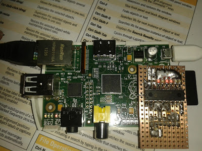
    I have been wanting to get an MCP23008 I2C port expander connected to my Raspberry Pi for quite a while. I finally got one and during my breaks from LabVIEW CLD exam preparation, made the circuit on some strip board. 


    Using the Quick2Wire Python I2C library makes getting this working really quick and easy. Just make sure you place your LED's the correct way around. I spent a bit of time debugging the I2C until I thought of checking the obvious. 

    Currently I only have the outputs working as I didn't have any switches with me. I'll add two switches and get that going next. 

    Here is the code that I used. I set up a little menu to select which LED to turn on or off. 


    Next I plan to get the software PWM working so that I can connect up to Cheerlights. Need to do some more studying and then will get that going. Also need some RGB LED's first.

    Until next time, happy coding.

    Greg

    Monday, 20 May 2013

    A week of LabVIEW courses at National Instruments

    Last week I sat my first two LabVIEW courses. I have been wanting to do some courses for a long time but have never really had the opportunity. Fortunately as I am not working at the moment, I got the time to do them. As I did my CLAD exam a few months ago, I decided to to LabVIEW Core 3 and LabVIEW Connectivity.


    LabVIEW Core 3 was on Monday to Wednesday and then LabVIEW Connectivity was on Thursday and Friday. The week was really packed in, but the amount of hands-on time kept us busy and focused.

    Over all I got more out of Core 3 and will definitely be using many of the concepts in my future programs. I have also thought back to some of my first programs and realised that I could have made them so much better in many ways. I am planning on doing my CLD exam around August so will be going over many of the topics in my practice programs. 

    I found Connectivity a more fun course where we learnt how to use many network tools and tools to include shared libraries from .net and many other programming languages.

    The examples that you work through for both courses are very in depth and explain the concept being taught very well. The instructors that lead the course are very knowledgeable and helpful about the course subject  and other questions and topics that arise during the discussion periods. 

    I highly recommend taking one or many courses that NI offer as this is a great way to learn quickly. The learning curve that I went through a few years ago when I learnt LabVIEW by myself would have been drastically shortened had I done some courses sooner. 

    Go on, give your NI representative a call and book a course today. You will not regret it one bit.

    Greg

    Wednesday, 24 April 2013

    Raspberry Pi temperature profile using LabVIEW

    Connected to my Raspberry Pi is a DS18B20 temperature sensor which I have mounted inside the case roughly above the processor. I wanted to map the temperature profile inside the case and have a visual representation of it. To do this I joined up a Python script, an SQLite3 database and LabVIEW.


    I only have one temperature sensor connected and the RasPi doesn't run very warm so this image is rather exaggerated. I'll explain a bit more later.

    So I started off by writing a Python script that runs on my RasPi. It measures the temperature and then logs it to a SQLite3 database that I store in a shared folder on a mounted USB flash drive. I have accelerometer data in the database too, but that will be added a bit later.


    That is all that happens on the RasPi. Next I wrote a LabVIEW program that queries the database over the network to get all the data. I need to do a bit of work on my query to just return the last line of data but that I'll add in future versions.

    To query the SQLite3 database, I used the this toolkit which works really well and is super simple to get set up. Once I have the temperature, I need to display it on in user interface. This is where Sensor Mapping Express VI comes in really handy.


    All you need to do is point to your .stl file and select where you want to the temperature sensors to sit on the RasPi. I used this model which I converted using Google SketchUp. This is where I had to use four dummy senors to be able to show the temperature difference. I have set the outside 4 sensors to 0 degrees Celsius and only sensor 0 is getting the temperature from the database. With more sensors this can be made a lot more accurate. As I said earlier, this is just to prove a concept for now.

    Every 100ms I query the database, build an array with the temperature data and then apply it to the Sensor Mapping Express VI. The temperature profile then changes according to the surface temperature of the RasPi.

    Here are the colours that I used for my mapping:

    Temperature vs Colour mapping:
    0 Celsius R-0 G-0 B-255
    21.25 Celsius R-0 G-255 B-255
    42.5 Celsius R-0 G-255 B-0
    63.75 Celsius R-255 G-255 B-0
    85 Celsius R-255 G-0 B-0

    I have already connected up an ADXL345 accelerometer which is acquiring tilt and pitch values, so my next step is to be able to move the  model in LabVIEW as I move my physical RasPi. Should be some fun for a few more hours.

    If you want a copy of my code, you can grab it over here.

    Please feel free to leave any tips, comments or questions below.

    Greg

    Monday, 22 April 2013

    Route static files for BottlePy web framework

    I have been using BottlePy on my Raspberry Pi for quite some time. I really like the simplicity of the framework and the ease at which you can get something up and running. The one issue I had, was that you could not load static css or js files. 

    There are ways around this, like placing your files in Gist and linking to the raw code, but this can be an issue when you want to run your webserver 'offline'. The documentation is not very clear on how to do this, so here is what I did to get it working properly. 

    This is the template that I use to route the static files. This is part of my main python code that runs the server.

    Then all you need to do is add your file names in the .tpl file. By doing this, your css, or js files can be stored locally so they can still be served if you are offline. 

    That is about it. I hope this helps because I really find this framework great to use and works flawlessly on my Raspberry Pi.

    Greg
    Source Control for LabVIEW using TortoiseSVN

    For a long time now I have been using LabVIEW, but I am not very diligent at using source control. Source control is one of those things that you never really need until it's too late. So this weekend I decided to install TortoiseSVN on my laptop to start out small, but get into the habit of backing up and recording the changes I make to my code. 

    To get up and running is rather easy. Go over to TortoiseSVN and download the install file. Once installed, you are ready to get going. 

    The first thing to do is make a folder somewhere to store your repository. I called mine svn_repos. Now right click, you will see an option for TortoiseSVN. Select the Create repository here option from the drop down menu. 


    Once you have created the repository, go over to the folder that you want to back up. Right click on the folder and select the import option under the TortoiseSVN menu. A window will pop up where you need to enter the path and details of the change. My folder name is TemperatureLogger so just change that in the path to suit your folder.


    Press OK and all the files in that folder will be backed up.

    Now you need to get a  working copy. I use the same folder but you can select any folder for your working copy. Right click on the folder that you have just imported and select the SVN Checkout option. Select your path and if it is the same path you will get a warning. Click OK and when the checkout is complete, you will notice that there is a green tick icon over the folder. When you make any changes to the files, that green icon will turn red.

    The LabVIEW part is to now install the JKI Toolkit for TortoiseSVN. Firstly you need to install the VI Package Manager. Once installed, search for TortoiseSVN in the user interface and install it. This takes a couple of minutes and needs your input for a few of the steps.

    Once everything is installed, open one of the files that you previously imported and checked out in LabVIEW. Make any change and then save it. You will now notice that there is a red icon over the files that have been changed. 


    In LabVIEW, go to tools > TortoiseSVN > commit. 


    Here you will be given the option to add a comment for the changes that were made. This helps you track your changes over time.


    You will now notice that icons over the files are back to green letting you know that you have backed up all your files.


    You can also get these options directly from Windows Explorer, but it is really convenient to have the option to back up your work directly from LabVIEW. There are many more tools to be used and they are explained pretty well in the documentation.

    Well I hope this helps you start to back up and document the changes that are made to your programs. Please don't forget that this can be used for any type of files, not just in LabVIEW. All you need to do is right click on the file or folder and choose the option under the TortoiseSVN menu.

    Greg

    Tuesday, 16 April 2013

    Raspberry Pi: Direct connection to Windows 7

    This is something I have been wanting to try for quite some time but never really found much info on how to do it. Well I sat down the other day to get it done and realised that it is MUCH easier than I expected.

    My objective is to directly connect my Raspberry Pi to my laptop using an ethernet cable. In the next few months I am going to be away from a decent internet connection but I still wanted to do some work on my RasPi. So my Google searching started, finished and here is what to do.

    The process uses a built-in feature of Windows 7 called Internet Connection Sharing (ICS). In a nutshell, you can use any Windows computer with more than one network connection, WiFi and LAN, and share the connection to other computers. 

    Firstly you need to set up the settings on Windows. You need to go to the properties of your disconnected LAN connection and click on the sharing tab. Then check the box to allow other network users to connect through this internet connection.


    The tricky thing to set up is the IP address that you are going to give the RasPi. You need to check the TCP/IPv4 settings under the Networking Tab. I picked an IP address and gave my RasPi a static address so that I know what it is when ever I use this connection.

    Next you need to power up your Raspberry Pi and connect to it some way. Either use a WiFi connection that is already set up, an ethernet connection to your router or using the serial port on the GPIO.

    You then need to set up the IP address by editing the interfaces file.
    sudo nano /etc/network/interfaces
    Change the part of the file that refers to your eth0 connection to look similar to below. You might have other settings in there like WiFi IP addresses and passwords but just leave those alone.
    iface eth0 inet static 
    address 192.168.137.184 
    netmask 255.255.255.0

    Once you have saved the interfaces file, send the shutdown command so that you can change over the connections. Once powered off, directly connect your RasPi ethernet port to your Windows ethernet port. You should be able to use both straight-through and cross-over cables. Now power up the RasPi.

    Once booted up, you should be able to log in with Putty to the static IP address that you set above. 

    And that is pretty much it. Another cool thing by connecting this way is that you should be able to power your Raspberry Pi from your computer USB port. This makes transport really easy as all you need is an ethernet cable and a USB cable to get up and running. 

    Hope this helps and if you have comments or questions, please leave them below and I'll get back to you as soon as I can.

    Greg