New domain and blog

New domain and blog
Please head over to my new domain to view my blog and current projects

Wednesday, 12 December 2012

Raspberry Pi meets TI LaunchPad MSP430

A few weeks ago I got a TI LaunchPad. With the help of a few tutorials I managed to get the basic input, output and UART working. As most of the examples that I could find are for CCS, I decided to go that route instead of IAR.

My next step was to get my LaunchPad working with my Raspberry Pi via the USB port. After a bit of playing around and installing a few programs, I managed to get it to work. Below is how I got a program  written, compiled and programmed onto the LaunchPad from the Raspberry Pi.

First you have to install a few programs with apt-get.
$sudo apt-get install binutils-msp430
$sudo apt-get install gcc-msp430

$sudo apt-get install msp430mcu

$sudo apt-get install mspdebug

$sudo apt-get install msp430-libc
You might have to run
$sudo apt-get update
before installing the modules.

Next run mspdebug to make sure that there are no errors. If there are no errors type exit to close the debugger.
$sudo mspdebug rf2500
Now that you have everything installed, we need to create the program. I use nano text editor to write my program.
$sudo nano button_ISR.c

This program uses the two LED's and one push button on the LaunchPad. When the button is pressed, an interrupt is generated and then the LED's are toggled.

Close nano saving the changes.

The program then needs to be compiled.
$sudo msp430-gcc -mmcu=msp430g2553 -g -o BUTTON_ISR button_ISR.c
The program should compile without any errors and now you are able to run the debugger.
$sudo mspdebug rf2500
Now program the device
prog BUTTON_ISR
and run the program
run
CTRL+c will stop the program running and exit will close the debugger.

In the next post I will show you how to communicate between the TI LaunchPad and Raspberry Pi via hardware UART and the USB connection.

Greg

Monday, 10 December 2012

Raspberry Pi: Edimax EW-7811UN WiFi Dongle

I recently bought myself an Edimax Wifi dongle to use with my Raspberry Pi. My router is hidden away so I got tired of running a network cable to my Raspberry Pi. The Edimax WiFi dongle was ideal as it is really inexpensive and very small.

It took a while for me to get it set up correctly but eventually I got there. To set up the WiFi connection, you either need a ethernet cable plugged into your Raspberry Pi or you need to connect via the serial port. I connected via the serial port with a FTDI USB to UART converter as this made it much easier to know when the network was connected. 

First of all plug the dongle into one of the USB ports and then reboot.I have not tested this in a USB hub but I am sure it will work the same. To make sure that the dongle has been started, run 
ifconfig
and make sure that wlan0 can be seen.


The next step is to see if your Raspberry Pi can see your wireless network. Run the following command and look for your network.
sudo iwlist wlan0 scan

Under 'Cell 01' I can see my network. Take not of your ESSID and you will also need your network password.

Once you have established that your Raspberry Pi can see your wireless network, you will need to edit the network interfaces file.
sudo nano /etc/network/interfaces
You will need to add the following:
  auto wlan0
allow-hotplug wlan0
iface wlan0 inet dhcp
wpa-ssid 'your ESSID'
wpa-psk 'your password'
Your interfaces file should now look like this. Note that I have set a static IP address so if you still use DHCP then you will not need the static IP address settings like I have.


Restart your network connection by running
sudo /etc/init.d.networking restart
and then run
ifconfig
and you should notice an IP address assigned to wlan0.

Now reboot your Raspberry Pi to make sure that everything is working in order.
sudo reboot
If your connection is up and running after the reboot, then you are all set to go wireless.

Greg

Monday, 29 October 2012

Raspberry PI: Bottlepy and Twitter Bootstrap

I have been using my Raspberry Pi for the last few months quite a lot. I am currently working on a temperature/environment monitor that logs temperature, using a DS18B20, and light conditions using an optical sensor. I also have two LED's and two buttons to test basic input and output.

I am developing the application in python using the BottlePy framework. I chose the BottlePy framework as it is a single file that you add, it is very small and it works with Python 3. To control my GPIO's, I am using the Quick2Wire library. To display the temperature data, I am using Google Charts.


This is a picture of the main temperature logging page so far.

However, the purpose of this post is to show how to integrate BottlePy and Bootstrap by Twitter. According to their website, Bootstrap is a "Sleek, intuitive, and powerful front-end framework for faster and easier web development."

To display this, I am going to use my GPIO code which reads buttons and turns on LED's through a webpage. 


To start off we need python file that will run as the server. Below is a snippet of code. The @route shows that this particular function will be run when /gpio us entered into the browser. The webpage is broken up into four sections. The first controls LED 1, the second controls LED 2, the third gets the state of both buttons and light sensor and then the fourth runs a .c file to flash the LED's.


Now we need to have a look at the html code that creates the webpage. By default, Bootstrap works with the user downloading the .css and .js file. These are then statically linked to the html code. When using the BottlePy framework, I haven't found a way to return a webpage template, AND a static file. Therefore I have found a link where the .css and .js files have been hosted. By using these links, you only have access to the default settings, but they are enough for what I am wanting to do.


You have to link to the .js and .css file and then by using certain classes that have been defined and explained on the Bootstrap website, you can get nice looking buttons, navigation bars, and tables. They have many options to use but these are the three that I used here for my site. 

When a button on the website is pressed, it sends the value back to the python function and the python code will perform the task. With the Flash LED button, the python code calls a .c file that has been compiled and runs when called. 

When requesting the button state, I return hex formatted colours to show the state of the buttons. These the colour in the table. 


The red shows that Button 1 has been pressed, the Green shows that Button 2 is not pressed and the Blue shows that the light level is currently light.

There are many different elements that can be added by using the Bootstrap framework. The documentation is really clear and easy to follow with many examples. 

If you get stuck or need some more explanations give me a shout.

Greg

Embedding Gist code into Blogger

I have been playing with my Raspberry Pi and Linux for a few weeks now. Most of the example code has been published on GitHub so I thought I'd give it a go and see what it's all about.

At first I tried to add a repository and then the code snippets. That didn't seem to work as I liked so had a quick look around and saw that you can add a Gist and embed that a lot better. You are also able to link to a raw piece of code. This will hopefully come in handy as I have an idea on how to use this. If it works I will cover it in another post.

All you need to do is create a GitHub account and add a new Gist. Save the Gist get the embedded link.

When you are writing your post, switch to HTML view and paste the script where you want it to appear in your post. You can then switch back to normal view to finish writing the post.

That's about it really. Pretty simple and quick to add code. This is much easier than some of the other methods that I have seen where you have to edit the HTML code of the template with custom java script code.

Greg

Thursday, 27 September 2012

Raspberry Pi: Changing time zones

By default the time zone on the Raspberry Pi image is set the the UK. As there is no RTC on the Raspberry Pi, when ever it is turned on, the time is synced. To set the time zone to your local area, in my case South Africa, the configuration of the tzdata package needs to be changed.

sudo dpkg-reconfigure tzdata


Select your territory.


Then select your local time zone.


As you can see the time zone has now been changed.

Greg

Monday, 10 September 2012

Raspberry Pi: Using Bottlypy to control GPIO

I have been trying for a few days now to get control over the GPIO pins through a webserver. There are a number of tutorials on the web but having very little web programming experience, I struggled to understand and follow the tutorials. 

After working through a number of examples, and not getting what I want, I came across the bottlepy framework. The tutorial on their website and the todo example show enough ways on how to get data to an html page and how to get data from an HTML page.

I have been super busy at work and also trying to get it to work so haven't had a chance yet to do a bit of an explanation on what I did.

To download the files I used click here.

You will need to edit your IP address in the index.py file.

Change to the directory on your Raspberry Pi and run $ python3 index.py

In your browser navigate to IPaddress:8080/index then follow the links. Have a look in index.py to see what pins I have used for the inputs and outputs.

Sorry this is so vague but as soon as I get a chance I will update this post with some more explanations.

Greg

Wednesday, 29 August 2012

Raspberry Pi: GPIO input and output

So I got my Raspberry Pi yesterday and am super excited. I feel like a 10 year old on Christmas morning. I had already loaded the the Raspbian image onto an SD card so as soon as I got it I powered it up and away it ran.

The first thing that I wanted to get working was the GPIO pins. I did a bit of reading and some basic python examples and away I went. Have a look at this website for a very decent crash course in python.

The first thing you need to do is import the GPIO module. This can be installed from here

Then you need to tell python that you are going to use the Raspberry Pi's pin numbers when referencing the ports. The direction of the port is then set.

Once the setup is complete, you can start your code. In my hardware, I connected a push button switch to pin 11 and pin 18 and an LED to pin 3 and pin 5.

import RPi.GPIO as GPIO

#use the Raspberry Pi pin numbers
GPIO.setmode(GPIO.BOARD)

#set the input with pull up control
GPIO.setup(11, GPIO.IN, pull_up_down=GPIO.PUD_UP)
GPIO.setup(18, GPIO.IN, pull_up_down=GPIO.PUD_UP)

#set the output pins
GPIO.setup(3, GPIO.OUT)
GPIO.setup(5, GPIO.OUT)

while 1:
 if GPIO.input(11):
  GPIO.output(3, False)
 else:
  GPIO.output(3, True)

 if GPIO.input(18):
  GPIO.output(5, False)
 else:
  GPIO.output(5, True)

Above is the python code that I used. If you want to download the file you can get it here.

Once you have the file saved, run it in python and by pressing the buttons, the LED's will turn on. To stop the program running, press CTRL+z.

Greg

Friday, 17 August 2012

C# dll for programming Microchip PIC's

In the test development environment, the need often arises where a microcontroller needs to be programmed before the testing can be completed. This can either be done with the development environment or through the command line if this method is provided for by the manufacturer. 

Programming in the IDE is nice and easy, but very slow and needs the user to press the buttons. Often in the test environment, this process needs to be automated with as little user input as possible. Here is where using the command line parameters comes in so handy. You will need this hard-to-find document which outlines the commands to use.

In my application I am programming the PIC18LF26K22 microcontroller from Microchip and using the MPLAB PM3 device programmer. To test the devices I am using LabVIEW and TestStand from National Instruments. 

There is a provision in LabVIEW where you can run command line programs, but I have found this to be a bit slow when interfacing with the PM3 programmer. This made me think of writing a C# dll to perform this task. Now I am no expert at C# programming, but am trying to learn where I can so thought this would be a good exercise. 

I started off be investigating the Process Class and found just what I was looking for. All you need to do is create a new object of the Diagnostics.Process class. Then build the string that you need to send. The make up of this string is explained in pdf attached above. 


public bool LoadImageToPm3(string pm3CmdPath, string port, string hexImagePath)
        {
            System.Diagnostics.Process proc = new System.Diagnostics.Process();
            proc.StartInfo.FileName = pm3CmdPath;
            proc.StartInfo.Arguments = "/" + port + " /P18LF26K22 /F" + '"' + hexImagePath + '"';
            proc.StartInfo.RedirectStandardOutput = true;
            proc.StartInfo.UseShellExecute = false;            
            try
            {
                proc.Start();
                strStandardOutput = proc.StandardOutput.ReadToEnd();
                proc.WaitForExit();
                int iSuccessful = strStandardOutput.IndexOf("Operation Succeeded");
                if (iSuccessful > 0)
                {
                    return true;
                }
                else 
                {
                    return false;
                }
            }
            catch (SystemException e)
            {
                return false;
            }
        }

This is an example of how to load an image onto the PM3. I build the string and then once I start the process, I read the standard output to make sure the the operation was successful.

The dll I wrote can handle loading an image to the programmer, program a device where the image is already on the programmer and erase the device. There are many other processes that can be performed but for the production testing that I am doing, this is all I need.

In the project attached, I also wrote a simple form application and a TestStand sequence to test the dll. You can find those files here.

By using a dll, I decreased my programming time from 60sec in LabVIEW to 15sec. When the device being tested only takes 30sec to test, an extra 45sec programming time is huge.

I hope this helps and if you need anything explained further, please leave a comment and I will try help where I can.

Greg

Tuesday, 17 July 2012

LabVIEW: Simulating keyboard events

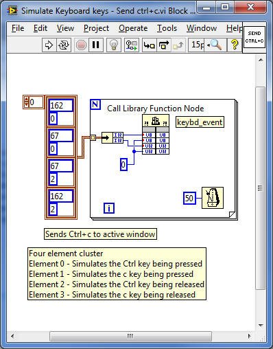
Another useful trick in LabVIEW using the user32.dll is to simulate keys being pressed on the keyboard. I haven't come across the need very often, however when using console applications, it can be necessary.

I ran into this problem while running a console application that runs a GPS simulator. Getting the application to run was easy and when the simulated trip is complete, the console closes automatically. The problem came in when I wanted to stop the controlling LabVIEW application. When I stopped the LabVIEW application and if the console was still running, I needed to close it and wanted to do it all in one step, instead of forcing the user to stop the LabVIEW application AND close the console window.

After some research I found out that the user32.dll has a keyboard event method so I decided to use that. I first had to make the console window active, find out how here, and then I would run this application as a sub-vi to simulate a Ctrl+C which was needed to stop the GPS simulation and close the console. 


What happens is that the two integers need to be passed to the dll. The first element is the decimal representation of the ASCII character that needs to be simulated and the second is what motion the button makes.

EG: 162 is represents the Ctrl key and 67 is the decimal representation for the ASCII uppercase C. The second integer that is passed to the dll is used to decide what the button is doing. 0 Simulates that the button is being pressed and 2 simulates that the button is being released.

Therefore, by writing each cluster to the dll in a for loop with 50ms delay between loops, Ctrl+C is written to the active console window which will stop the GPS simulation and close the window.

To download the example VI, use this link.

Greg

Friday, 13 July 2012

LabVIEW: Making a window active

A small issue that I have been trying to resolve is when a LabVIEW application runs and multiple windows are open, the need is often there to bring a window to the front as some stages of the application. 

Now I am sure there are many ways to perform this task, but the easiest and most reliable way that I found is to use the user32.dll that is part of the windows installation. This dll is easily accessed by using Call Library Function Node. This can be found in Connectivity >> Libraries & Executables.


The three methods that are used are FindWindowA, SetForegroundWindow and ShowWindow. By wiring these us and adding the correct window name that you want to bring forward, when the program is run whatever window name is selected will be brought to the front. 

There are many other tasks that can be performed by using the user32.dll. I have used it in a few other places in my programs and will add some more posts in the future of where it can be used.

To download the example VI, use this link.

Greg